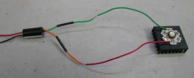
Here I've soldered the wires from the LED to the
driver. It's important to make sure the + and - connections are
hooked up properly as the LED will not light up if you hook it up
backwards.
By putting heat shrink tubing on the wires before
soldering them, I can just slide the heat shrink over the solder joint
and then heat it (I used a lighter) to make sure the wires don't touch
and short out. I like heat shrink tubing the best, but you can
use electrical tape as well. If using heat shrink, make sure to
shove it a ways away from the wire ends before soldering or else the
heat from the soldering iron will shrink it before you're ready.
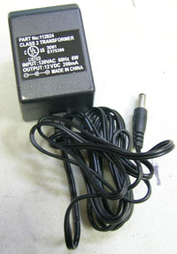
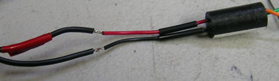
Here's a cheap "wall-wart" type power supply I'm
using. It's rated for 12V at 200mA or 2.4Watts. My LED will
only be using around 1W, so this supply should be fine. I've cut
the end off because I don't have the mating connector handy. I
plugged it into the wall and used my multimeter to determine which wire
was + and which was -. I put some red electrical tape on the +
wire so I could easily tell them apart.
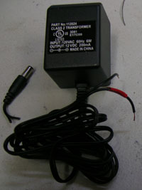
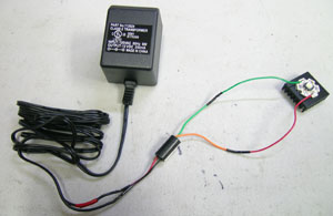
Once I identified which wire from the power supply was +,
I soldered the two wires to the input of the bucktoot driver.
Again, it's important to make sure the polarity is correct before
applying power. Hooking things up backwards could damage the
power supply, driver, or LED.
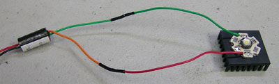
Here is the completed electrical system. The
wallwart plugs into the wall and sends power to the bucktoot
driver. The driver converts that power to way the LED likes it,
and then sends it on to the LED. The next step is to hook it up
and make sure it works!
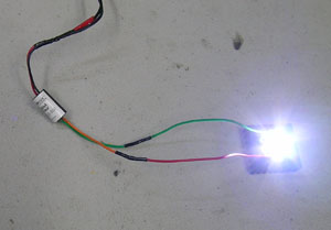
Yay! It works! These LEDs are bright!
After waiting for the spots in my vision to go away, it's time to put
the whole thing together.
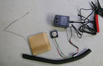
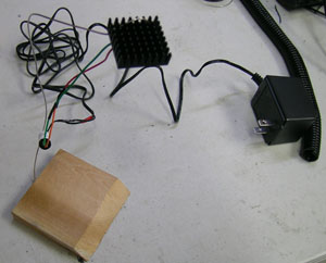
Here are all the parts for my desk lamp. I have the
power supply, driver, and LED w/ heat sink from before. Also in
the picture are a block of wood with some mechanic's wire (a stiff but
repositionable steel wire) screwed to it and some split-loom style
tubing.
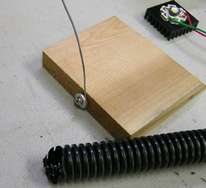
To attach the mechanics wire to the wooden base, I just
bent the wire around the screw using my needle-nosed pliers and then
screwed the screw into the base. I added a washer to help pinch
the wire against the wooden base and keep it from turning.
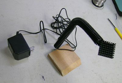
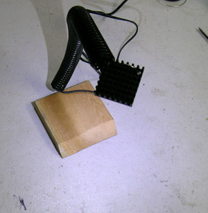
After drilling a couple of holes in the heatsink, I bent
the mechanic's wire through the holes in such a way that it holds the
heat sink. It's a bit difficult to see in this picture, but the
heatsink and LED are about 8" in the air over the base. You can
see the bucktoot driver hanging in the air from the wires. We'll
hide that in just a moment.
I've hidden the colored wires, the mechanic's wire and the
driver inside the split-loom tubing. My lamp is complete.
After plugging it in, I immediately start using the
lamp. It's awesome! It's a lot brighter than my camera
makes it look, and it makes it really easy to read those tiny numbers
on electronic components or to identify resistor color bands. My
camera makes it look a little blue, but its actually a very nice white
and it does a much better job with the resistor color bands than the
overhead fluorescent lights I have in my lab.
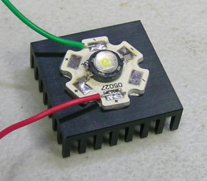 Here I've mounted an LED Star to a heatsink. While
the 05027 Star usually carries a Luxeon K2 LED, here I've replaced it
with a Seoul P4 that I was able to get my hands on.
I put some red and green wires on the star and
then glued it to the heatsink using Arctic Silver thermal
adhesive (make sure you use the adhesive version of the Arctic Silver if
you want to glue the LED to the heat sink. Arctic Silver also makes a thermal grease,
but you would have to drill/tap the heat sink and use screws to attach the star if you
wanted to use that).
It is important to have a good thermal path between the
LED and the heat sink to keep the LED cool. This is because LEDs
get dimmer when they get too hot, and it can also shorten their
lifetime.
Here I've mounted an LED Star to a heatsink. While
the 05027 Star usually carries a Luxeon K2 LED, here I've replaced it
with a Seoul P4 that I was able to get my hands on.
I put some red and green wires on the star and
then glued it to the heatsink using Arctic Silver thermal
adhesive (make sure you use the adhesive version of the Arctic Silver if
you want to glue the LED to the heat sink. Arctic Silver also makes a thermal grease,
but you would have to drill/tap the heat sink and use screws to attach the star if you
wanted to use that).
It is important to have a good thermal path between the
LED and the heat sink to keep the LED cool. This is because LEDs
get dimmer when they get too hot, and it can also shorten their
lifetime.
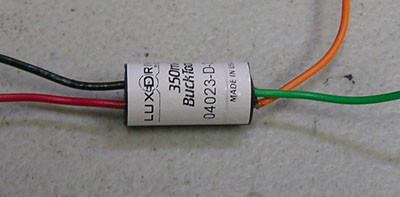 This is an LED driver called a Bucktoot made by
LEDdynamics. The neat part about this driver is its small
size. It's only 3/4" long! The driver runs the LED with a
constant current (350mA). Because most electronics run with a
constant voltage instead of constant current, it is much easier to get
a constant voltage power supply. The driver converts the constant
voltage from the power supply into the constant current that the LED
needs to run properly.
This is an LED driver called a Bucktoot made by
LEDdynamics. The neat part about this driver is its small
size. It's only 3/4" long! The driver runs the LED with a
constant current (350mA). Because most electronics run with a
constant voltage instead of constant current, it is much easier to get
a constant voltage power supply. The driver converts the constant
voltage from the power supply into the constant current that the LED
needs to run properly.